Part of my brain seems to be in my hands, because no matter how long I study a topic, my understanding feels superficial and ghostly until I’ve grappled with it not just conceptually, but literally. So, I try to build stuff.
My dad was a carpenter for all my childhood years that I remember, a craft that was replaced by the “construction worker” as standardization and mass production gradually took much (though certainly not all) of the skill out of it. Watching him operate a table saw was just part of my young life. It fascinated me that he could use that scary thing (“whirling death” was my pet name for it later, when I worked in a cabinet shop) to turn uninteresting pieces of lumber into anything he wanted or needed.
Enough of that marinade soaked into me that for nearly all of my adult life, I’ve had a table saw. Not the same one through the decades, but a series of them. The times when I was living in apartments, my saw would usually be in a friend’s garage where I had access to it. Sometimes in storage, but that felt disempowering—what if I needed to make a thingamajig?
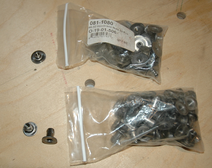
Of course, a table saw all by itself is like a zoo animal. To live a full life, it needs to drag a whole ecosystem of other tools, parts, and hunks of wood with it. So those have accumulated too, and been “drug” from state to state and decade to decade. I’m doing more metal than wood now, but a few days ago I had a problem to solve, and scrounging around in the fasteners drawer, I found two untouched bags of hurricane nuts, which were just the thing. I had no idea I had them and I have no idea when I bought them; I would guess the late ’90s.
What is a hurricane nut? Well, one vendor gushes: “Once you use a Hurricane nut, you will never go back to an ordinary T-nut.” Pretty exciting, unless you don’t know what a T-nut is either. Both are doohickeys for embedding some female metal machine threads into a piece of wood so that you can use a metal machine bolt to fasten the wood to something else. (I wonder if this male/female thread naming business is flying under the radar of those who are trying to get rid of gender stereotypes in language. I also wonder if clockwise/counterclockwise makes any sense to today’s kids. I wonder lots of things.)
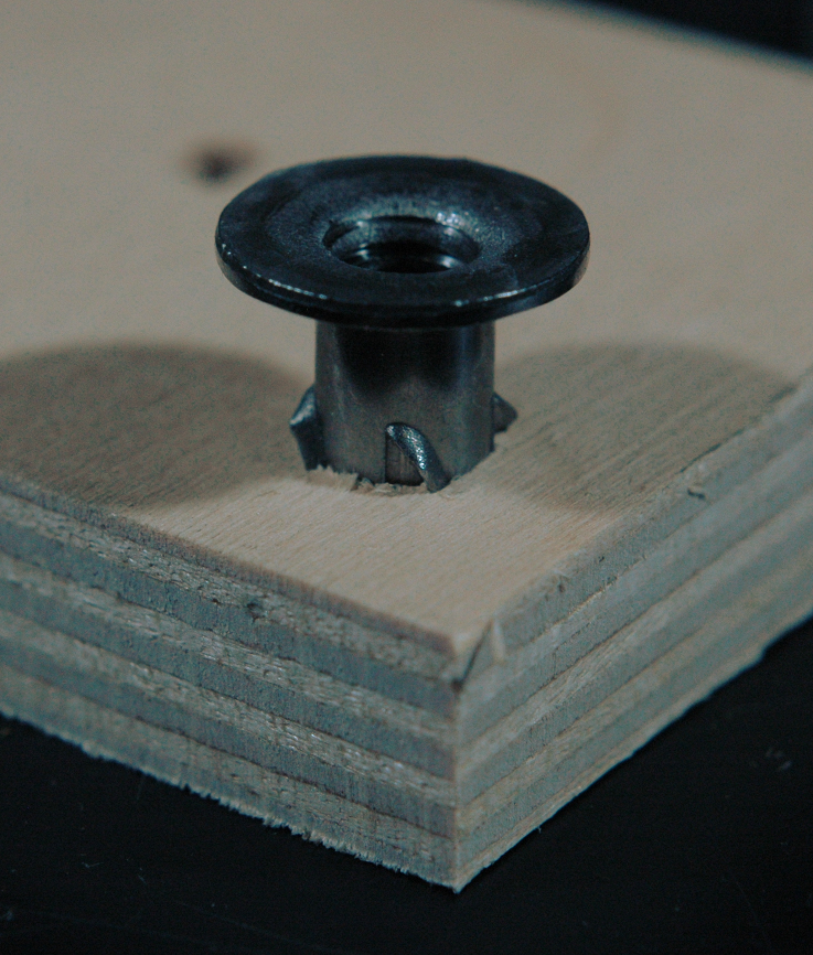
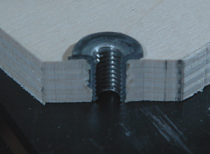
Let’s say you have a piece of Baltic birch plywood (one of the seven wonders of the modern world), as pictured. And you want to bolt something heavy, like an induction motor (even higher on the list of wonders) to the plywood to keep it from moving. Wood screws aren’t ideal, especially for repeated assembly/disassembly. So, you drill the right-sized hole in the plywood, press or hammer in a hurricane nut, and you have threads that are as one with the wood. I can’t find any history of who invented them or why they’re called hurricane nuts. They’d be useful for boarding up houses in the tropics before a storm, but maybe that’s just marketing.
What is the particular problem I’m trying to solve? Well, suppose you were me, and you wanted to build a prototype of a pumped-storage hydroelectric system. To put energy into the water, you use a motor and a pump to push it uphill through a pipe. To get the energy back, you use the water, flowing back down through the same pipe, to spin a generator.
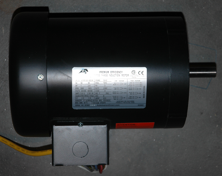
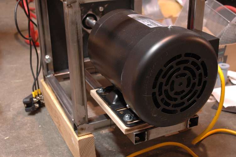
Here is a 1-horsepower (that’s 746 watts), three-phase induction motor. It weighs about 40 pounds, but more importantly, it can exert a lot of force, so it needs sturdy mounting.
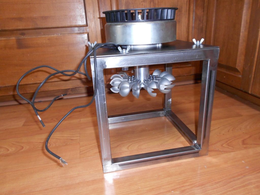
And here is a 1000 watt (rated) three-phase permanent-magnet generator. It made an appearance here before and it’s meant to be spun by water hitting a Pelton wheel, which came with the package.
By any sort of industrial or commercial standard, the amount of power these things deal with is puny, minuscule. Barely even one hair-dryer unit. Even so, they’re big enough to challenge my skills and shop setup. So I first thought about what the fully functional prototype would look like, and worked backwards from there:
Step C. Full prototype: a pipe runs up a hill. The top end of the pipe is roughly 100 feet (we’re thinking small) above the bottom end. At the top, a reservoir holds water, about a minute’s worth at full flow. At the bottom, (a) another reservoir of the same size; (b) the motor, connected to a centrifugal pump (maybe the one I salvaged from my defunct hot tub) to pump water up through the pipe; and (c) the generator/Pelton wheel, to make electricity from water flowing back down. That’s too hard to start with, and I haven’t found a hill to borrow. So, simplify:
Step B. Garage-scale prototype. Instead of a hill, use air pressure in a tank to simulate gravity. There are still two reservoirs (smaller, just enough for a few seconds of operation) and the other components are the same. Still too hard to start with, so:
Step A. Skip the water for now. No pump, no Pelton turbine—just use the motor to drive the generator directly. Then you can at least characterize the motor and generator, see if they can run at the advertised power levels, and measure how efficient they are.
Step A seemed to be a bite that I could realistically chew, so I’ve been working on it. I can control my induction motor with good precision using a VFD (variable frequency drive), something I’ll discuss in a later post. The mechanical problem is to mount both of these powerful components so that one can spin the other. I need to make sure the shafts are very well-aligned with each other to prevent damage to the bearings in each piece.
I have exact specs for the dimensions of the motor, and locations of bolt holes, etc., because motors like this are sold by the millions and have become very standardized. The generator is more of a specialty item, but I have all the key dimensions for it as well.
If I had a milling machine and a metal lathe, I could do this the right way, and work from the specs to make a mounting system that would be just right without any tweaking; just bolt it together and go. Instead of a milling machine and a metal lathe, I have inherited stinginess. My dad always had tools that weren’t quite crap, but were somewhat closer to crap than excellence. (To be fair, the average garage hobbyist today has tools of better quality than were even available in his day.) When I took the plunge into metalworking, I bought a welder, but it had to be about the third-crappiest one I could find. When you want the third-crappiest, Harbor Freight is the place to go. (That’s catchy—I should work in marketing.)
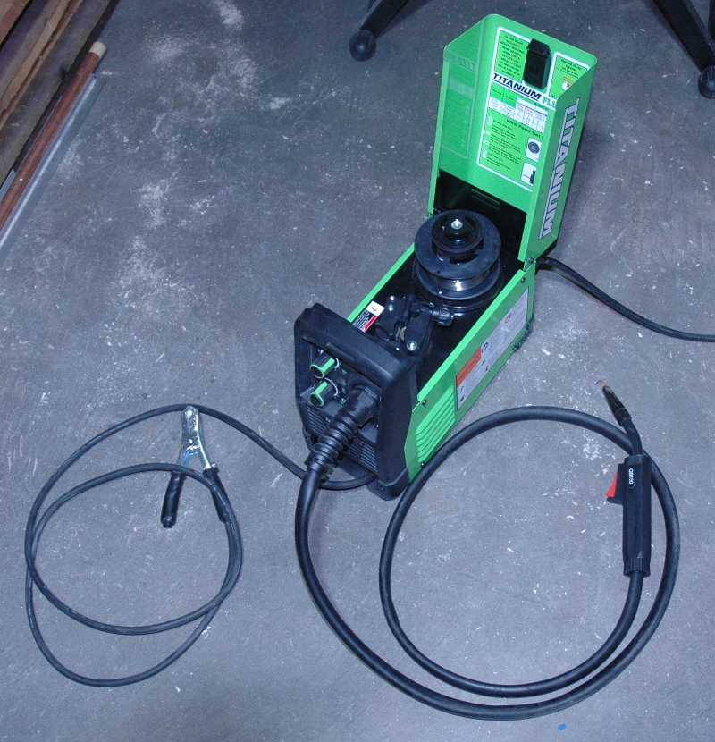
It cost about $160 on special from their website, and I remember it showed up just about the time we all started to wonder if the cardboard boxes that UPS were dropping off were covered with Coronavirus. It’s a flux-core welder, meaning that it doesn’t need a high-pressure steel bottle of shielding gas like a MIG or TIG welder would. It also runs on regular wall-socket 120V, which is all I have in the garage. The downside of flux-core is that it tends to make uglier welds, and the process gives off a lot of nasty smoke that’s bad for your lungs long-term.
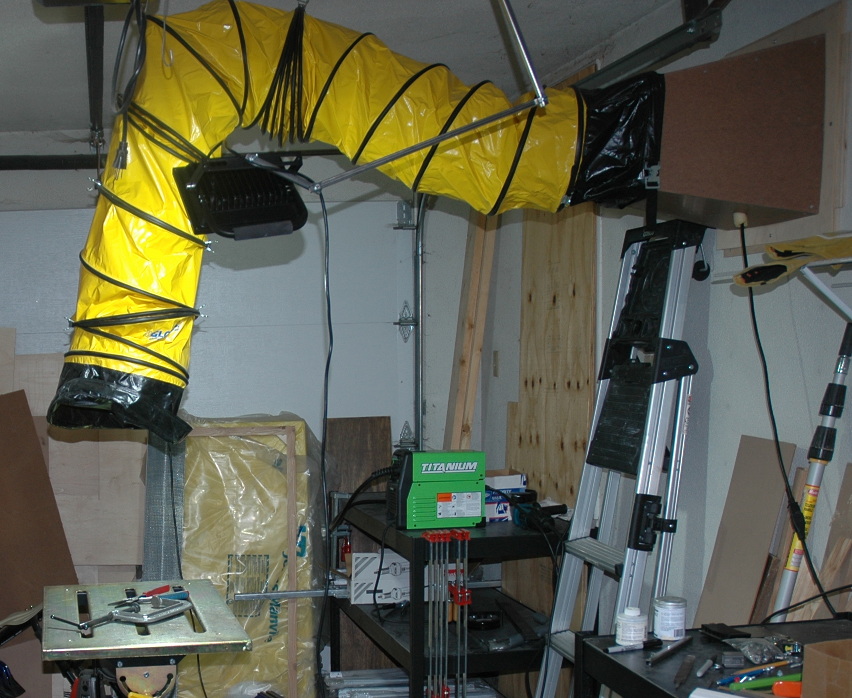
So I needed good ventilation. I bought a vent fan and a long flexible duct from Amazon, chopped a hole in the garage wall (using a diamond blade in the angle grinder to cut through the stucco), built some adapting and mounting pieces from wood, and hung the mouth of the duct over my (ultra-cheap, Harbor Freight) welding table. I use binder clips to adjust the height of the intake. It moves more than enough air to keep the noxious welding smoke out of the room and my lungs.
After watching many YouTube videos about welding, and practicing on some scrap metal, I bought $200 worth of steel from a supplier down the road (that’s the price point where free delivery kicks in). The thing I bought the most of was 1″ square hot-rolled steel tubing. This is hollow, and the wall thickness I bought is about 1/16 of an inch. It’s cheap, good for welding, very strong and not too heavy (I could easily carry several 20-foot lengths at a time while the driver and I were unloading the truck).
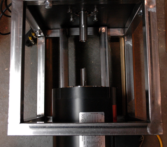
I built a frame from the 1″ tube in the shape of a cube, one foot on a side. That’s shown in the picture up above with the Pelton wheel momentarily attached.
Next I built a sort of sled out of the same material to mount inside the cube and support the weight (and torque) of the motor. This is simply a long, skinny rectangle. The sled is attached to the cube by three bolts, which pass through these holes into slots in the cube.
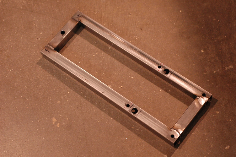
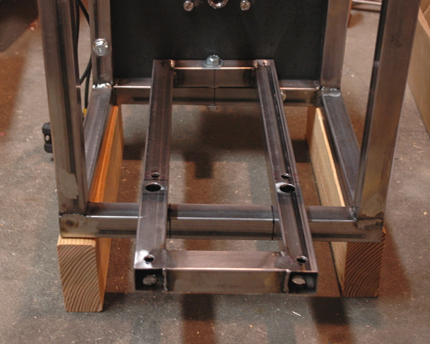
The slots give me coarse adjustment on side-to-side location and rotation around the vertical axis. I didn’t have a good way to make the slots, so I bought an electric die grinder (basically a Dremel tool on steroids) and some carbide burrs. Die grinders are tricky, it turns out, and the business end of the first burr I used is now hiding out under some lumber. Learning! But the slots were made. For fine adjustment, the motor is attached to a plywood “skid plate”.
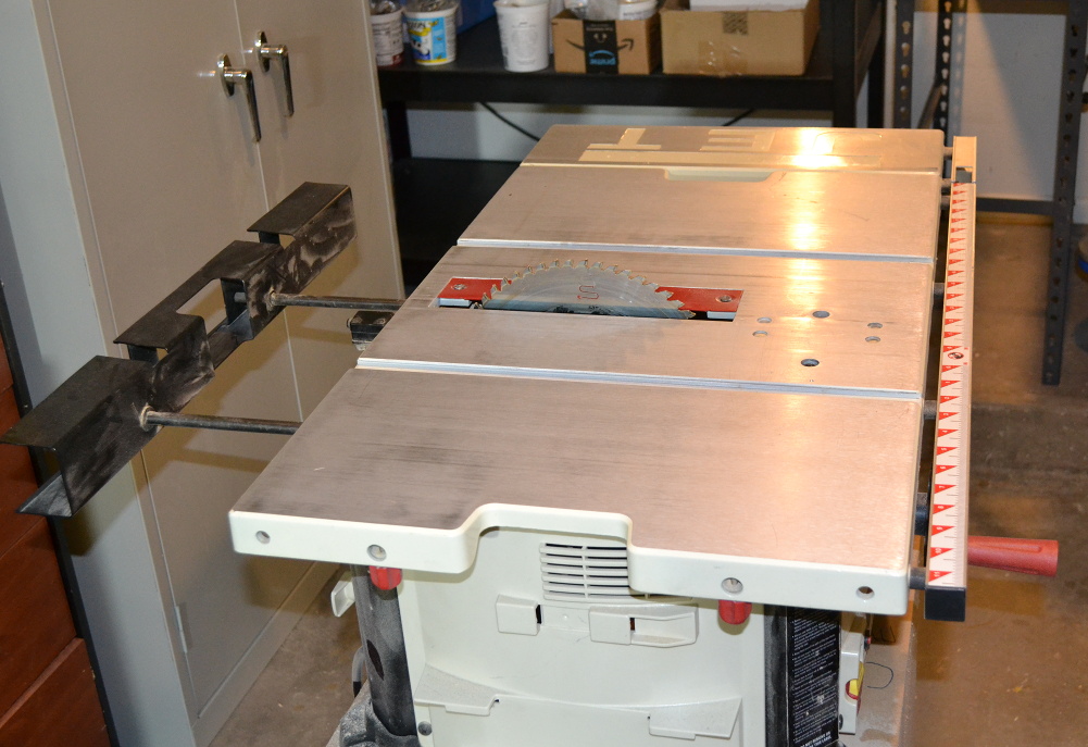
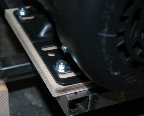
Here’s a closer view. The skid plate is fitted with four hurricane nuts, into which four threaded rods (bolts with the heads cut off) are Loctited, so that a washer and nut at each corner holds the motor to the skid. The bottom of the plywood is smooth, so the motor can slide freely (in two axes plus rotation) on the sled.
Here’s how it looks from above, before sliding the motor forward to close the gap between the shafts.
The remaining adjustments I need are the vertical height of the motor, and the tilt of the motor in the shaft-up/shaft-down axis. Both of these are handled by putting brass shims (rectangles of sheet brass in assorted thicknesses, about 1″ by 3/4″ in size) between the skid plate and the sled. The motor and skid plate are then locked in place with clamps.
The final task is to make the shafts rotate together, while allowing for the slight misalignment that remains after all my fiddling with the motor position. The shafts are also different sizes (the motor has a 5/8″ diameter shaft, but the generator’s shaft is 7/8″). I spent a few days trying to 3D print some shaft collars, and struggling with the usual hassles of 3D printing—filament that absorbs water from the air and doesn’t melt as it should, prints that either don’t stick to the base plate or stick too hard, “elephant’s foot” making it impossible to print perfectly sized holes—before getting smart and remembering that what I needed is a stock industrial item:
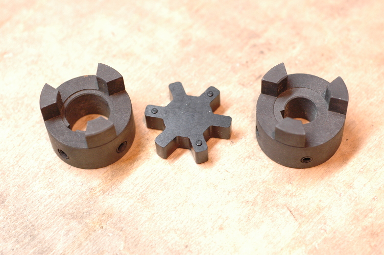
This is one common type of shaft coupler. The middle part is some sort of firm rubber; the other two parts are steel. Different parts for the same series fit together, so I bought one end in 7/8″ diameter and the other in 5/8″ diameter, which takes care of the different shaft diameters. (You can see the differently sized holes in the picture above.)
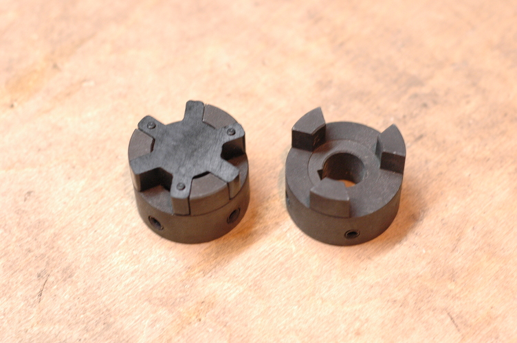
The rubber part fits in the middle…
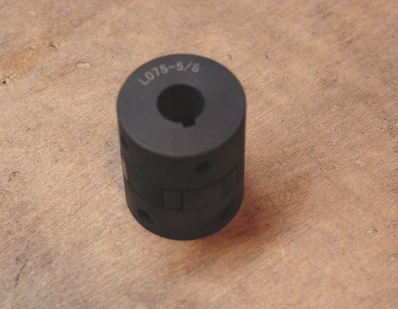
…and when fully assembled, it’s captured between the steel parts, transmitting rotation while allowing just enough leeway for imperfect alignment of the two shafts.
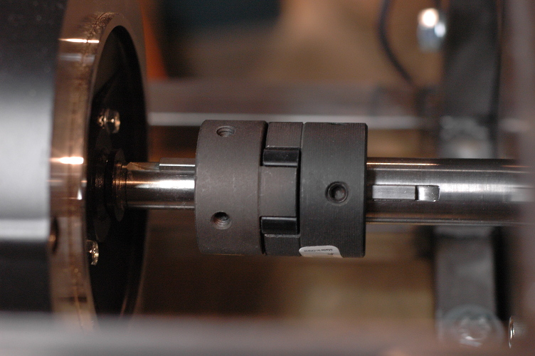
Each half piece is fastened to its shaft with two set screws, plus a square key (you can see the keys in this picture). The keys fit halfway into slots in the shaft ends, and halfway into slots in the coupler ends, locking things together for positive rotation. But the only thing connecting the motor to the generator is the rubber spider piece, so everything runs quietly with no metal-to-metal contact. All for about $15 worth of parts. Sometimes it’s better to work with the global economy than to fight it.
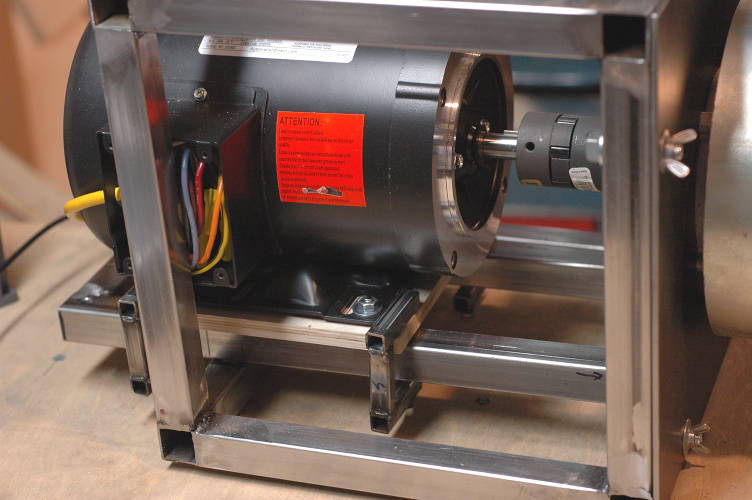
Here’s everything put together: the generator on the right, fixed to the outer frame; the motor, on its plywood “skid,” which is moved (and shimmed) on the steel “sled” to align the shafts, then held in place with four shop-made clamps, two on each side. If this were a really permanent setup, I’d replace the clamps with some solid bolt arrangement (or even weld things in place, a surprisingly viable strategy), but once I’ve learned all I can from this, the motor and its mounting fixtures will go away. The next step (“Step B” above) will be to use the motor to drive a water pump.
But first, I need to supply power to the motor to make it run at various speeds, and measure things like how much power the generator is making as the motor forces it to spin. That Misadventure In LearningTM will get its own post.