I’m calling this the start of “Series 2” because, as I’ve looked at promising Encapsulated Pumped Storage (EPS) sites, I’ve noticed some recurring conditions—specific to the Mojave Desert—where, by tweaking the previous EPS design, we could build grid energy storage even faster and at even lower cost than before. The improvement is significant enough that I feel compelled to lay it out as my preferred solution.
I’m going to keep this series as short as possible, leaving Series 1 in place as introductory and reference material. This post and the next will discuss the new water storage design, and the third (and perhaps last) will talk about a real-world example site in California.
What is EPS, if it’s not the specific solution discussed in Series 1? Fundamentally, it’s pumped storage where the water is fully contained by inexpensive polymer materials, preventing evaporation and reusing the same water indefinitely, and without large monolithic reservoirs.
One outstanding benefit that results is that it can be built in places where no other kind of hydroelectric facility could be (because of terrain, aridity, or both). It also holds promise for shortening the traditionally long construction times that have plagued hydro plants of any kind. What kind of site would allow us to start building EPS tomorrow?
Think of the Gordon Butte project in Montana as the easy end of the spectrum for closed-loop pumped storage: flat on top, flat at the bottom, not too much horizontal difference between them, and a climate where evaporation isn’t a deal-breaker. Excavation (per unit of water stored) is about as simple as it could get. Reservoirs at such sites are usually approximately circular (sometimes kidney- or amoeba-shaped), because a circle has the largest area relative to its perimeter length of any two-dimensional shape, which reduces cost, particularly if you’re encircling the water using a built-up concrete dam. Here’s the Gordon Butte plan again:

Now consider a somewhat less ideal topography: a flat, but tilted plane, with a moderate slope that’s in the range of 3% to 10%. This is not uncommon in the American West. Sometimes it’s an alluvial fan or slope at the foot of a line of mountains1. Sometimes it appears to be a tilted block2.
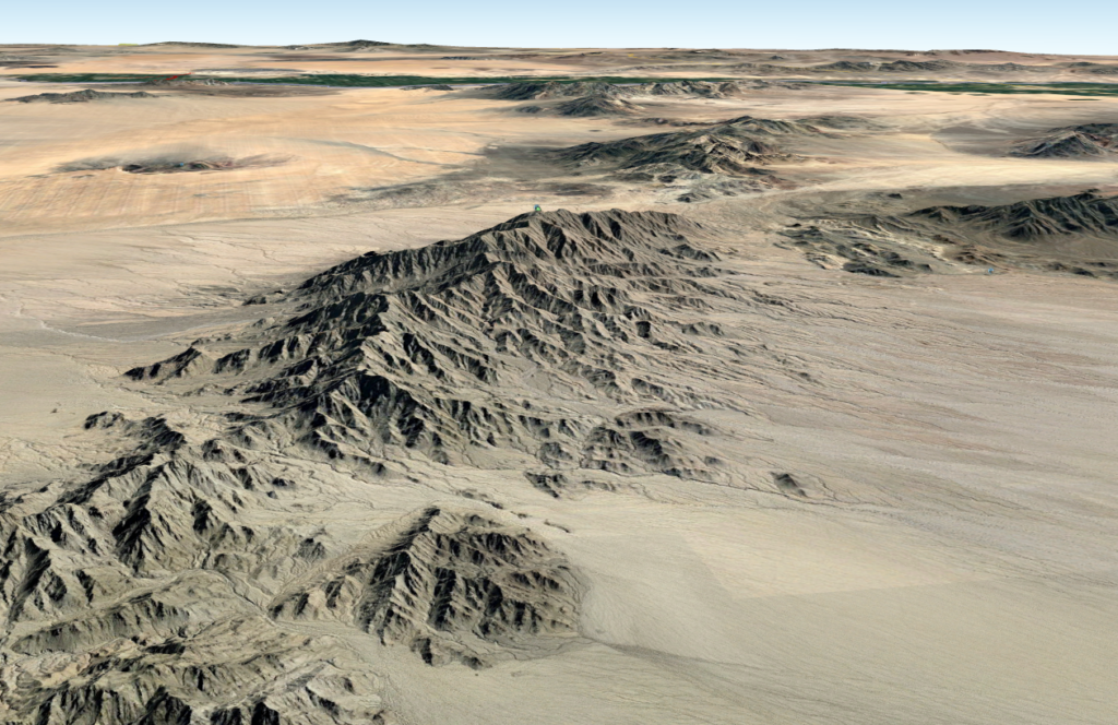
It looks like this because the region receives almost no rain. In most climates, these tilted plains would be deeply eroded by rivers and streams, covered in vegetation, and all the sharp edges would be rounded off. Here, the tilted plane is intact, and we can exploit that.
Building a circular or amoeba-shaped reservoir on this kind of terrain would require a great deal of excavation, to reach bottom depth on the uphill side. The uphill slope would naturally be vulnerable to erosion, so its gradient would have to be kept gentle, requiring more excavation. Or, you could build a retaining wall from concrete to keep the hill above from sliding into the reservoir, but at that point you’re almost building a dam, and the ideals of “inexpensive” and “fast” become hard to achieve. The use of large amounts of concrete or steel would also mean the project owes a substantial CO2 debt (“embodied carbon”) before it even comes online, meaning it takes longer for it to become a net reducer of greenhouse-gas levels.
Canals
But what you could do, much more simply, is dig a canal (a reservoir that’s long and narrow instead of round) that runs sideways across the slope, at a constant elevation (i.e. along a contour line). By limiting the cross-slope distance, you can limit the amount of excavation per unit of water stored. And excavated material only has to be moved to the sides of the canal, a simpler and faster chore than moving earth a longer distance from the center of a round reservoir to its edge. At the same time, total water storage is only limited by how far the canal can run cross-slope on the terrain of interest3.
Another big advantage comes into play if we retain the EPS feature of allowing sub-reservoirs, within a storage field, at different elevations. The obvious strategy is to build another canal, more or less parallel to the first, at a suitable distance up- or down-slope. Now you can fill in a two-dimensional area with water storage, without having to dig the whole area out to a single elevation. (Canals at different elevations can’t be directly connected to each other; how they do connect to the rest of the system will be discussed below.)

What is the fastest, cheapest, and lowest-carbon way we can build these long, narrow reservoirs? First, excavate a trapezoidal ditch. The slope angle is chosen based on the stability of the terrain. The more stable the soil is, the steeper the canal walls can be. The ends of the canal have the same slope. Here’s an idealized version of how it would look on an absolutely flat location:

In practice, it will look a little different, especially on a sloped site (which is where this sort of design really makes sense). A key principle of fast and affordable excavation is to move as little material as possible, as short a distance as possible. So instead of hauling away the material we remove as we dig the canal, we’ll push it to the sides to make berms to keep runoff water out, and to expand the capacity of the canal, something like this (the particular slope shown, 7%, is only for illustration but is in the range we want):

Lining the canal
Next, line the bottom and the sides of the ditch with a reinforced flexible membrane. There’s an entire industry devoted to making such materials, known generally as “geomembranes” or “geotextiles,” and used for retention of everything from potable water to toxic slurry. The requirements for this material, in our use case: it needs enough abrasion resistance and burst strength to bridge small gaps, and it needs to last for decades without developing leaks. It doesn’t need exceptional tensile strength, because the weight of the water is supported by the terrain, not by the membrane. It doesn’t need to be drinking-water safe, or resistant to strong chemicals.
The jobs of the membrane are (a) preventing loss of water to seepage; (b) stabilizing the soil; (c) preventing soil material from contaminating the water; and (d) preventing weed growth into the water.
The membrane material will extend beyond the trench walls and onto a small raised berm on either side, where it can be anchored. One reason for the berm is to divert runoff water from rain or snow around the canal, rather than into it. Geomembranes are sometimes protected with a layer of earth, rock, or concrete on top, but in this application, we shouldn’t need to do that, at least not in the actual water-carrying part of the canal. We can use suitably-sized rocks outside that area (and particularly over the edges of the membrane) to keep everything stable:

To build the liner, strips of the material, cut from large rolls, can be laid crosswise on the canal and then heat-welded or otherwise joined into a continuous sheet:

Due to the long, narrow canal shape, it’s possible that a complete liner could be welded up on a factory floor, and then rolled into a very large cylinder for transport to the site. If not, seam-welding in the field is very commonly done for this sort of product and should not be an obstacle.
Covering the canal
The canal lining will prevent water loss to seepage, but in our typical dry, hot environment, evaporation is a much greater worry. So our canal needs a floating cover, of flexible material that is opaque (to keep sunlight out of the water, reducing heat input and preventing growth of algae and other freshwater-dwelling life), has a high albedo (so solar energy is reflected rather than absorbed), and stays in contact with the water as it rises and falls, to keep the water from evaporating.
When the canal is completely dry, i.e. when it’s first constructed, the cover will be touching the liner all the way across. In operation, we’ll never let the canal drain below a certain level, because we need the water to flow in and out freely. Even so, the water level will change, and a cover that’s the right width at low water will have too much material when the canal is completely full. We could just size the cover for the low-water condition and let it randomly fold itself to deal with the excess material when the canal’s full:

That might work just fine, or it might not. But there’s another issue we have to address: rain and snow. These will create another layer of water on top of our cover, which will become a problem if it isn’t removed. All this has been worked out by the floating-reservoir-cover industry, for applications like municipal drinking water reservoirs, so we don’t have to reinvent any wheels. The approach they take is to build fold lines into the cover using small floats and weights permanently heat-sealed into the cover, so that as it drains and fills, it behaves deterministically, not randomly:

Here’s how this design would look from above, using a “double-Y” shape to accommodate the sloping ends:

Besides giving the excess material a place to go when the reservoir is full, these fold lines naturally create a trench in the surface into which rainwater will collect, making it easy to remove with small pumps. It won’t rain or snow often in our desert environments, but once in a great while, there’ll be an exceptional weather event that dumps lots of water into the canal at once. We need to be ready for these rare events and make sure the site can keep running without interruption.
We can build these canals at whatever width and depth suits the terrain. In the limiting case of very flat terrain, we could make the “canal” a large square, if we like. We might choose not to even in that case, though. The long and narrow design has several benefits:
1. Excavated earth never needs to be moved very far—it’s just pushed across the width of the canal. (Software would be used to lay out the canal such that there’s no net movement of fill material into or out of the immediate vicinity of the canal; all material removed is used for berming, and for localized filling of dips in the landscape.) This will be faster and simpler than removing large amounts of material from the center of a large, circular reservoir.
2. No point in the canal is more than half the canal width from land. This will make some construction and repair operations easier. For example, we can run steel cables across the width to ferry materials and even workers across, without needing to touch the cover.
3. Both the liner and the cover span known widths, and so it should be possible to prefabricate larger sections off-site.
4. If we standardize on two or three canal widths, experienced gained by building them repeatedly with the same crews and equipment should lead to better procedures, faster construction and fewer errors.
5. Of course, the biggest benefit is the ability to build significant water storage on sloping terrain, rapidly, with no use of concrete or steel.
What Size Canals?
For the sake of example, suppose the soil characteristics of our site can support a 50%, or 2-to-1 slope. (This is about 26.6 degrees.) I’ll use the customary trapezoidal shape and will arbitrarily set the bottom width at 1/5 of the top width (I’m not trying for a fully optimized design, just something reasonable). All the canal drawings in this post match this specification. If the width from bank to bank is 100 meters, here are the other dimensions:

The bottom is 20 meters wide, and the sloping sides are 40 meters wide and 20 meters deep. The length along the slope is 44.7 meters. The total width of the liner is 109.4 meters (not counting the extra material outside the canal itself, as shown earlier). That means that the floating cover is also 109.4 meters wide, so it is in full contact with the liner when the canal is completely empty. When it’s full, of course the cover “folds” to a width of 100 meters.
The cross-sectional area is 1200 square meters, which means that for each meter of canal length we have 1200 cubic meters of water storage. But we never want to fully drain it, so let’s estimate 1000 cubic meters of usable storage per meter of length. (Since the ends are sloped too, they add some storage, but for now let’s ignore that.) So, a canal 1 kilometer in length would store 1 million cubic meters of water. The mass of this much water is 1000 kilotons.
Earlier, I computed that one KK (kiloton-kilometer) of elevated water yields 2.8 megawatt-hours of electrical storage (at 100% efficiency). So if we have a 1-kilometer-long upper canal that’s 1 km higher in elevation than its lower twin, we could store 2,800 MWh, or 2.8 gigawatt-hours of electrical energy.
From here on, I’ll factor in a round-trip efficiency of 75%. This means that if an EPS system takes 1000 watt-hours of energy from the grid, uses it to pump water uphill, and lets the water flow back downhill later, 750 watt-hours of energy will go back to the grid. 75% is an estimate based on reported numbers for existing pumped hydroelectric systems, and knowing typical efficiencies for the individual components. So to revise my last number, the effective storage for a 1-km-long canal at 1 km head would be 2.8 * 0.75 = 2.1 GWh.
How many Raccoons is that?
Raccoon Mountain, which (as discussed earlier) is the largest pumped-storage facility in the world by energy, reportedly stores about 36 GWh, so I refer to this amount of energy storage as “one Raccoon.” (Raccoon Mountain has 320 meters of head, so it has to store and move about three times as much water as an equivalent system with 1 km head.) With the 100-meter-wide canal design, we would need 36 / 2.1 = about 17 kilometers (10.6 miles) of canal at both top and bottom to equal 1 Raccoon. There are many sites where this would be feasible.
If a site evaluation shows that the soils can handle steeper slopes (when protected by a geomembrane liner), then the canal dimensions can be adjusted accordingly, resulting in a narrower and deeper trench, lower material costs, fewer cubic meters of excavation, and a shorter construction cycle. Sites that are too unstable for a 50% slope, or present other excavation challenges like hard rock to be broken up, should probably be skipped or saved for later.
If we want more storage, and the site is amenable, we could scale up the canal design, perhaps by a factor of 2.5, making it 250 meters across, bank to bank, and 50 meters deep:

Since cross-sectional area scales as the square of the linear dimensions, this very large canal has a cross section of 7,500 square meters. It stores 6.25 million cubic meters of usable water per km of length, and 13.1 GWh of energy per km at 1 km head. If we can build 10 km of this size of canal at top and bottom, we could store 131 GWh, or 3.6 Raccoons of energy. In Part 16 I stated that, based on my modeling results, 50 GWh of storage, combined with a lot of wind and solar, would make New Mexico’s electrical grid 100% carbon-free, so such a system would decarbonize two and a half New Mexicos.
10 km (6.2 miles) is not very long for a canal, but it still seems unlikely that we’d find a site where we can build a canal that long and 250 meters wide, at a constant elevation, and arrow-straight. The task is considerably easier if we can build (a) a canal with some curves in it, or (b) multiple canals.
Curves could be accommodated, as long as they’re gentle (large radius compared to the canal width, which means narrower canals could bend more sharply). We don’t want sharp curves that would interfere with our ability to standardize all parts of the canal-building process.
We can also build multiple canals, either at the same elevation, or at different elevations. There is another benefit to multiple canals that we don’t want to lose sight of, and that’s the ability to start with a small system and scale it up over time. If we can start with a 1-kilometer-long canal that stores “merely” 13.1 GWh of electricity (70 Hornsdales, i.e. 70 times the largest Li-ion battery grid storage currently in production), and add to it later, everything will be faster and easier.
The easiest way to do this would be with a chain of two or more straight or slightly curved canals at a common elevation, which could be at sharp angles to each other, interconnected by large-diameter pipes which are buried at the elevation of the deepest part of the canals. The large diameter and short length of the pipes would minimize energy loss to friction. The first canal could be built with a stub pipe already in place, and closed off. Then, when it’s time to build a second canal, the first one would stay in service, and the second would be built with a pipe meeting the stub of the first. When the second is ready, the system would be brought down just long enough for the cap to be removed and the two pipes joined together.
Plumbing
To simplify, the plumbing of a hydroelectric plant, starting at the upper reservoir, consists of these elements (each of which can be single or multiple):

1. The reservoirs—canals in this case. They are shown here on the same axis as the penstock, but since they’ll actually be aligned with elevation contours, they’ll often be more or less crosswise; any orientation is possible.
2. The headrace. This is a relatively horizontal pipe or open channel that carries water from the upper reservoir to the top of the penstock. (In EPS, of course, there are no open channels—all water is enclosed.)
3. The penstock. This is the tube carrying water down to the powerhouse, which is the lowest elevation in the system. It can be vertical, or sloped, but either way, it spans the elevation difference that makes the system work. It has to withstand high pressures.
4. The powerhouse, with its turbines, valves, and pipes. Here, the pressure in the penstock is used to drive the turbines. The water exits the turbines at close to atmospheric pressure.
5. The tailrace. In a hydroelectric power plant, there is no lower reservoir, so the tailrace is just a path to get the exhaust water from the turbines back into the river, which carries it away. In a pumped storage plant, the exhaust water is saved for reuse, so the tailrace is a pipe that slopes upward slightly to pump the water into the lower reservoir. The turbine needs to be lower than the reservoir for two reasons: (a) so that gravity will feed the water back out of the lower reservoir to the pump when it’s time to pump it back uphill, and (b) to prevent cavitation in the pump.
In a pumped-storage system, obviously, all these components run in both directions. Another element to be considered is the surge tank (or tanks), which protect the other components (especially the penstock) from potentially damaging pressure transients. There are different designs, sizes, and locations for surge tanks, the need for which is a function of how quickly the system’s operating speed and/or electrical load are changed. This need is reduced if system changes (such as valve openings and closings) are performed slowly and smoothly.
The downside to this is that the slow-motion policy limits how fast the system can react to demand changes. If we choose not to build fast reaction time into our EPS system (which would require, among other things, ample surge tanks), then grid managers can rely on alternatives such as batteries or flywheels to take care of short-term peaks and valleys in demand. EPS can be built for fast response, but if quick and inexpensive construction is more important, some reaction time might need to be sacrificed.
Valves
Multiple canals on contours can be located at different elevations if that’s the best way to make use of a particular site. But in order to connect two canals at different elevations to the same penstock (or tailrace, at the bottom), we would need transient valves to connect each canal to the penstock while shutting off the other. These valves would need to be extremely large, which would add time and cost to the overall project.
Instead, we can take advantage of the fact that if the site is large and is built incrementally, it is bound to have multiple turbines. (For example, the New Mexico scenario I modeled required a minimum of 2.2 GWh of generating/storing power, which is beyond the range of a single commercial turbine—300 to 500 MW per turbine is more typical.) If we’re going to have multiple turbine/pump/motor/generator sets, that gives us the option to have multiple penstocks as well. (As a side benefit, this would make the subsystems autonomous, so any sort of downtime would affect only part of the system while the rest keeps working.)
If we do this, then each canal elevation within a storage field can each have its own dedicated headrace and penstock (or tailrace for the lower field), going straight to the powerhouse, and there is no need for any valves outside the powerhouse. (Valves will be needed inside the powerhouse regardless, to shut off the water supply to/from the turbines and/or pumps, to divert water away from the turbines in case of emergency, and so on.) We’ll just choose sites that are compatible with this. Exploitation of “trickier” sites can come later. (There are other reasons for sites to not make the first cut, such as lower head, longer distance to markets necessitating long transmission lines, land-use obstacles, and so on. That doesn’t mean those sites aren’t worth using, only that they shouldn’t come first.)
Installing the plumbing components
How will we build, support and stabilize the headstock, penstock, and tailrace? And allow for the inevitable thermal expansion of these components, transient hydraulic forces, and so on? These problems have been solved in many ways over the last 100 years.
The problems aren’t particular to EPS. The only thing that’s somewhat different is the priorities, with speed of construction, embodied emissions (i.e. the greenhouse gases generated during the mining, manufacturing and installation of the item in question), and hot-weather operation all assuming greater significance. The time-honored approach of boring or blasting tunnels through rock is not compatible with speed of construction, and the use of concrete (as either pipe material, or liner) is a poor choice due to embodied emissions. With current technology, that pretty much leaves steel pipe as the only good option for the high-pressure components, which are penstocks, turbines, pumps, and valves. (The embodied emissions of steel are bad, but not quite as bad as concrete, and we will use less of it. Of course, huge efforts are being made to find ways to produce these materials with a smaller greenhouse-gas footprint, and with luck, this issue will be less significant in the future.)
The headraces and tailraces operate in a much lower-pressure regime, and at some point, fiber-reinforced polymer (FRP) technology should advance far enough to replace steel for these parts of the system. In fact, we might be there already.
There are a number of well-known issues with steel pipe. Rust is one: not only can it weaken the structure, requiring very costly repairs, but rust inside the pipe roughens the surface, drastically increasing hydrodynamic losses. Coatings and liners have been developed to address this issue. Rustproofing the exterior can also be achieved with coatings. For a system meant to be low-maintenance for many decades, a combined approach is best: rustproof everything, and also prevent water from getting where it shouldn’t, i.e. pipe exteriors.
Given all these requirements, here’s an approach that seems worth investigating:
- Plan a route for the headrace, penstock, and tailrace that will only require excavation, not supporting pipes above the ground. (In other words, all along the route, the bottom of the pipes will be at or below the pre-existing elevation of the site at that point, as shown in the site plan above.) Excavation may need to be deep (i.e. in excess of the pipe diameter) at some points, but the best route will minimize this. (The headrace and tailrace need to be lower than the reservoirs they service, so they’ll definitely be underground for all or most of their routes, which should be as short as possible.)
- Excavate the route as a trench, removing enough material to leave space around the pipe at all points. Put supports in place to locate the pipe in final position. (These are only for installation and aren’t intended to take the full static and dynamic loads on the pipe when in operation.) Install the pipe (normally welded together in sections), and do any coating, weld testing, or other post-assembly operations while the pipe is accessible.
- Now fill in the space around the pipe with aggregate—rock, gravel, and sand, using vibratory equipment and careful selection of materials to make sure the space is completely filled. The aggregate will be the main support for the pipe.
- Continue adding material until a ridge is raised above the surrounding terrain, and place a long strip of impermeable geofabric material over this ridge, extending a fair distance to either side. This can be held in place with more aggregate (sized large enough to resist erosion). The ridge will cause water to run off to the sides, rather than entering the trench to potentially cause erosion and rusting.
Using aggregate materials obtained either onsite or as close as possible, this solution will make for speedy construction, and a minimum of embodied emissions. The pipe can always be accessed from inside, but if access to the pipe exterior is absolutely needed, a section of the aggregate and cap can be dug out and replaced later.
This scheme will keep the temperature of the pipe much more stable than if it were exposed to summer sun, winter night skies and so on. This in turn will reduce length change of the pipes due to thermal expansion (which will still occur and must be planned for, but at a lower magnitude).
At any given site, there may be parts of the route where this solution isn’t feasible, or must be modified. For example, where the penstock route is very steep (which is desirable for keeping its length as short as possible), aggregate fill might not reliably stay in place. In these areas, one of the other well-understood historical approaches to penstock mounting, either above or below the surface, can be used.
The Powerhouse: Can We Build It Faster?
The powerhouse is where the turbines, pumps (if separate from the turbines), and motor/generator units live, along with related equipment, such as valves and perhaps electrical components like transformers. These are heavy, expensive pieces of machinery. The moving and/or water-carrying components experience very large forces, and so they need appropriate mounting to a stable platform. Finally, the turbines need to be at a lower elevation than the lower storage, to prevent cavitation. The powerhouse needs to be large enough for components to be installed, and removed occasionally for inspection and maintenance. (A large gantry crane is usually part of the structure, for lifting heavy components.)
All these factors are why some hydroelectric facilities have a powerhouse that’s excavated from solid rock and completely underground. But that’s a good recipe for slow and costly construction. Such a luxury might have been all right in a time when climate disaster was not hot on our collective heels, and engineers could plan many decades into the future, but not now, when every month counts.
So, thought should be given to how the lead time for constructing a powerhouse could be reduced. (Reductions in carbon footprint and cost would also be welcome.)
The equipment needs a heavy, stable, and level platform, and that almost certainly means concrete, particularly in the soft alluvial soils (good for canal building) that are anticipated at the lower end of typical EPS sites. Other than the floor, the rest of the structure could probably be steel. A steel cylinder, made of prefabricated sections, would minimize material use and construction time, and should be suitable for resisting the forces of alluvial soil at a moderate depth.
Consideration should also be given to size. One of the core benefits of EPS is modularity/expandability. An initial system might consist of a pair of canal reservoirs connected by a single penstock. Rather than building a powerhouse big enough to house any possible future build-out of the system, it might be faster to build a space just big enough for the generating power of that penstock (whether that’s one turbine, or several). Get that online and contributing as quickly as possible, and then build a second system alongside the first with its own penstock, pair of reservoirs, and powerhouse. This would allow the powerhouse design to be completely modular and standardized, instead of customized to the site.
About Floating Reservoir Covers
While it seems intuitively obvious that a floating impermeable cover can prevent water from evaporating, engineers need proof. Intuition isn’t enough when the use case is the Mojave Desert in the summer, with temperatures well over 100 degrees F, and getting hotter by the year.
Vendors certainly (if unsurprisingly) think it works. This photo is from a vendor called BTL Liners:
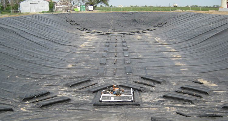
Think of this as a very short canal of exactly the type I mean. Here we see the cover in its fully collapsed condition, when the reservoir is empty. The double-Y shape of the cover is clear, with twin rows of embedded floats, between which are embedded weights (as in the diagram I showed earlier). This is the system that controls the shape the cover will assume when the reservoir is filled. In the foreground is, I would guess, a floating platform for a sump pump, whose job is to pump out rainwater that falls into the reservoir, as I discussed above4. To turn this into an EPS reservoir, we’d extend its length as needed, provide a much larger than normal pipe and manifold at the bottom for water to flow in or out, and we’d make it out of white/reflective material for rejection of solar heat.
Quoting from the BTL site, “Floating covers are geomembranes fabricated from durable plastic geotextiles […] Floating cover systems stop evaporation loss by preventing the dry air from contacting the water in a pond, reservoir or open tank. Floating cover systems reflect a portion of the incoming solar radiation and act as a barrier to the passage of water vapor. Additionally, floating covers can prevent evaporation caused by the wind, which is another way to conserve water in ponds and water storage tanks. Many floating cover systems can be fabricated in black or white reinforced polyethylene (RPE), or with black on one side and white on the other. White floating covers are ideal in the summer months and in desert, arid climates. White covers keep the temperatures down and help prevent evaporation by reflecting the sunlight off of the system, rather than absorbing it. When attempting to prevent evaporation in an open water setting, such as an irrigation pond or water storage tank, the amount of reduction can be influenced by the material of the floating cover system. Floating cover systems work most effectively when made from a material with a low transmission ratio, as well as with high reflection and absorption ratios. Floating covers are an effective way to prevent or reduce evaporation, especially in arid, desert climates that are susceptible to drought.”
BTL, of course, has a product to sell, so if that hurts their credibility, here’s an academic article: “A Review of Evaporation Reduction Мethods from Water Surfaces,” from the Moscow State University of Civil Engineering5. “Floating continuous covers generally make an impermeable barrier that floats on the water surface to reduce evaporation. Polystyrene,wax and foam have been tested as used materials for making floating continuous overs, but polyethylene plastic has proved to be the most acceptable and durable material for covers of this type.Tests have shown that floating sheets such as E-VapCaps can reduce over 95% evaporation from open water reservoirs.”
Besides evaporation, there’s another reason to cover, and line, hydroelectric reservoirs, one that I only learned about recently: The reservoirs themselves may emit significant amounts of methane and other greenhouse gases, as organic matter in the reservoirs decays. This overview article in the journal BioScience, “Greenhouse Gas Emissions from Reservoir Water Surfaces: A New Global Synthesis6,” reports: “We estimate that GHG emissions from reservoir water surfaces account for 0.8 (0.5–1.2) Pg CO2 equivalents per year, with the majority of this forcing due to CH4.” 1 Pg (petagram) is 1015 grams, a billion tons.
The details of the article suggest that it wouldn’t be much of a problem anyway for EPS in hot deserts; the decaying organic matter has to come from somewhere, either from plants that were growing in the reservoir area before it was flooded, from ongoing plant growth in the water, or from inflows of carbonaceous material into the reservoir from areas that drain into it. (Since the opaque cover will block most sunlight from reaching the water, algae and other aquatic life won’t have an energy source with which to grow.) The amount of organic material in hot, arid regions is probably so low that greenhouse-gas emissions from its decay would be negligible. Pumped-storage facilities in wetter, cooler regions, with uncovered reservoirs, would need to take these issues into account.
Dust
Dust storms are a problem in areas without vegetation to hold the soil in place, including the Mojave. At times, dust will accumulate on our floating canal covers. If it’s thick enough, it might interfere with the operation of the cover as water levels change. Its weight might also cause the cover (which is buoyant, but no thicker than necessary, to control costs) to begin to sink in places. We’ll need a dust-removal system that can be deployed when needed.
One strategy would be an air cannon, or scaled-up leaf blower, to blow dust off the cover. This could be mounted on a truck for deployment to any of the canals as needed.
Heavy rains would tend to clean the covers, by rinsing dust into the channels to be pumped out with the water—the sump pumps would just need to be able to handle the suspended particles (which is not an unusual requirement). Heavy dust followed by light rain would be the most challenging situation, since it could produce mud, which would be hard to remove. To avoid this, it would be important to remove heavy dust as soon as possible if rain is in the forecast. To clean mud from the covers, a water-spraying truck would need to be available. A quantity of non-potable water for cover cleaning would need to be kept on hand in a small reservoir separate from the energy storage system.
Can this only be built in the Mojave Desert?
No, it’s just that the Mojave is particularly rich in the sort of terrain that we need to make contour canals a good solution: the upper and lower storage areas both have to have long contours of constant elevation that are straight or gently curved, with only moderate slope (perhaps 10% or less) in the cross-contour direction. We also would prefer, for rapid construction, soils that are amenable to excavation with bulldozers, instead of rock that needs to be broken up. Finally, the hostile climate of the Mojave means that there are vast areas of land that are devoid of human habitation or economic benefit, yet close to metro areas. (Endangered species and habitats must, of course, be taken into consideration.)
There are many promising EPS sites outside the Mojave, but as EPS is a new approach, credibility will need to be established, so the first systems should be built on ideal sites where there are as few extra problems as possible. For this scheme, based on contour canals, those ideal sites are likely to be in the Mojave.
How many people live in suitable regions for this sort of storage?
I’ve said before that the states west of Texas and south of Oregon, including Hawaii, are the ones where EPS is feasible. Adding up the populations of those states7, I get 63 million people.
If we can tolerate the long transmission lines to Texas, another 29 million people live there. For scale, Los Angeles currently gets a significant amount of electricity from the Intermountain Coal Plant in Utah, which is about 480 miles away. So EPS storage could benefit Texans in the western and central parts of the state. But beyond that, the rest of America will have to get its storage some other way. (Unless we were to build a long HVDC transmission line to, say, Chicago, but clearly that’s not possible.)
Next: Encapsulated Pumped Storage, Series 2, Part 2: Hydrodynamics
- See this online book for more than you want to know about alluvial features.
- “Tilted type block mountains have one gently sloping side and one steep side with an exposed scarp, and are common in the Basin and Range region of the western United States.” (https://en.wikipedia.org/wiki/Fault_block#Fault-block_mountains)
- Thanks to commenter Ed C, whose bags-in-pits comments got me thinking in this direction.
- For much more about floating covers, see “Floating Reservoir Covers, Good Design Practices,” published by the American Water Works Association.
- E3S Web of Conferences 97, 05044 (2019), https://doi.org/10.1051/e3sconf/20199705044
- BioScience 66: 949–964. https://doi.org/10.1093/biosci/biw117
- CA, AZ, CO, UT, NV, NM, WY, and HI; numbers from https://www.infoplease.com/us/states/state-population-by-rank