A real-world example will make it much easier to visualize what the numbers are trying to tell us. At this point, we don’t need to design a full system down to the smallest details. I would like to set forth a scenario that would provide enough energy storage to be interesting. What I mean by “interesting” is, I suppose, “big.”
Since I live in New Mexico, I think it would be “interesting” to get my state off fossil fuels and onto renewables. How much storage (power times duration) would that take? Here are some ballpark numbers.
Public Service Company of New Mexico, or PNM, is the dominant electrical utility in the state. It serves the largest city (Albuquerque, with a metro population of about 900,000) and a total of over 500,000 customer accounts (households and businesses).

The state’s Energy Transition Act, a bill passed in 2019, “…requires the state (now one of the country’s top oil, gas, and coal producers) to get 50% of its energy from renewables by 2030 and 80% by 2040. By 2045, it must go entirely carbon-free.” Converting from always-available fossil fuel generation (like PNM’s 847 MW San Juan Generating Station, to be closed by 2022) to intermittent wind and solar will require a large amount of energy storage.
Assumptions
PNM’s hourly electrical demand is published by the U.S. Energy Information Administration, or EIA1. By downloading this data and summing it for all of 2019, I get a total demand for the year of 13,779 GWh. Dividing by 365 gives a daily demand of 37.8 GWh.
Seeking to validate this number, I found this document, the 2017 PNM IRP (Integrated Resource Plan). A table on page 19 shows 2016 sales, broken down by category. The total for 2016 is 12,280 GWh, which is in line with my 2019 number (with 2019 reflecting a reasonable 12% growth over 3 years).
One rule of thumb (which is a very rough approximation) is that storage equal to one day’s generation, combined with sufficient wind and solar capacity, will cover 90% of an area’s needs (the remaining 10% requiring fossil fuel, nuclear, or other backup capacity2). By this standard, we would need 38 GWh of storage. You could call that a heavy lift, given that in the previous post I stated that Bath County Pumped Storage Station was, at 24 GWh, exceeded only by Raccoon Mountain, which at 36 GWh is the largest pumped-storage facility (and therefore the largest storage facility of any kind) in the world. While I have no doubt that EPS can reach and exceed that capacity, I’d rather start by discussing a less ambitious prototype.
So let’s look at only the residential portion of PNM’s demand. From the same table, this was 3,190 GWh for the year of 2016. Adding 12% for growth to 2019, and converting to daily usage, that’s about 9.8 GWh per day. Let’s round that up and use 10 GWh (10,000 MWh) as our energy storage goal for our hypothetical facility.
How about power? We don’t have hourly data for just the residential part, so we’ll need to estimate. If the residential 10 GWh were used evenly through the 24 hours of a day (which of course it isn’t), that would be about 417 MW. So let’s set our goal as 400 MW, with the understanding that we can adjust this in the design later.
So the first part of our specification is: an encapsulated pumped storage plant that stores 10 GWh of energy, and can charge or discharge at a peak power of 400 MW. The duration will be 10,000 / 400 = 25 hours.
Where would this fall on the list of storage facilities in the previous post? In energy terms, it’s more than twice as big as Gordon Butte (4.3 GWh), and just a bit bigger than Dinorwig (9.1 GWh). Nothing can currently touch Raccoon Mountain’s 36 GWh. And our prototype weighs in at 54 times the energy storage of Tesla’s Hornsdale lithium-ion battery facility. It would definitely be “interesting.”
Power-wise, at 400 MW, we’re the same as Gordon Butte, but much less than Dinorwig’s 1800 MW and Bath County’s 3000 MW. But we’re well ahead of Hornsdale’s 100 MW, of which the long-term storage part is only 30 MW.
Those are the electrical specs (setting aside issues like response time for now). What mass of water would we have to move to do it? That depends on the hydraulic head, and as I stated before, one of the desired features of encapsulated pumped storage is to operate at relatively high head. I’m going to stipulate a head of 1 kilometer (or 3,280 feet). The greater the head, the less water we have to store and move, which has many benefits. But if it’s too extreme, usable sites will be very few, and we’d also risk leaving the comfort zone of well-established engineering practice, where we’d rather stay. A head of 1 km corresponds to a maximum pressure of 98 Bar, 97 atmospheres, or 1,422 pounds per square inch. For comparison, heavy equipment hydraulic systems often operate at 350 Bar or more (but handle a lot less fluid).
Here are the hydraulic heads of the pumped hydro systems discussed before: Gordon Butte, 314 meters; Dinorwig, 536 meters; and Bath County, 400 meters—all far exceeded by our thought experiment. The practicalities of running a system at 1 km head will be covered later.
Now we can compute the mass of water that needs to move between the upper and lower storage areas, separated vertically by 1 km, to store 10 GWh of energy. We’ll assume 100% efficiency for the moment, knowing that we are more likely to end up somewhere around 70-80% in reality.
I’m going to introduce a unit I find handy, which is the kiloton-kilometer (or “KK”). It’s the amount of energy it takes to raise 1 kiloton of water (1000 tons, or 1 million kg) a vertical distance of 1 km against the force of gravity. One megawatt-hour equals 0.357 KK. So if we have 1 km of head as specified, and 1000 tons of water (which is 1000 cubic meters), we can store 2.8 megawatt-hours of energy.
We want 10 GWh of storage, so we need 3,570 KK. At 1 km head, that’s 3,570 kilotons of water—3.6 million cubic meters. In Imperial units, about 3,000 acre-feet, or 950 million gallons of water. The system needs to be able to store that much water entirely at the upper elevation when fully charged, and entirely at the lower elevation when fully discharged. Well, we knew it would be big. (Practically speaking, we would certainly want to start with much smaller prototypes and work up to that sort of scale.)
That takes care of energy. What about power? We want 400 megawatts of electrical power. This power equals (again assuming 100% efficiency) the rate at which gravitational potential energy is lost by the water as it falls. That’s the product of the mass falling, times the rate of descent, per unit time. 2.8 megawatts equals 1 KK per hour, so to get 400 MW, we need 143 KK/hour.
At a head of 1 km, that’s 143 kilotons of water per hour moving through the turbines. A ton of water is a cubic meter in volume; converting to seconds, the volume flow rate is 143,000 / 3600 = 40 cubic meters per second. None of that is specific to EPS; any pumped hydro plant with the same specs would have the same flow rate.
Siting
Let’s take a first look at where a system like this might be built. What makes a good site for encapsulated pumped storage? First of all, we want our 1 km hydraulic head. Ideally, we would like to have billiard-table-flat surfaces at the upper and lower elevation, sufficiently large to fit all our water storage. We know we’ll have to settle for something less perfect in practice. We also want our upper and lower storage areas to be as close together horizontally as possible. This is because of the penstocks, the large pipes that carry water between the two areas. First of all, the longer they are, the more they’ll cost, and they’ll have to be quite strong to withstand the water pressure in our high-head system, so the material won’t be cheap. Secondly, water flowing in pipes loses energy, and the smaller and longer the pipe, the more energy it wastes. Larger diameter pipes lose less, but cost more, so it’s best for both efficiency and cost to keep the penstocks as short as possible. The ideal situation would be a vertical cliff between upper and lower storage areas, so the penstocks are also vertical, and exactly 1 km long. We know we won’t find that terrain feature in perfect form, either.
NOTE: This post does not reflect my latest thinking on water storage. Please see the new summary.
Next, let’s take a look at how much area our storage areas will need. We’ll refine this later, but for now, we’ll pick a height for our water containment tanks, see how much area a reservoir of that depth would need, and then add a packing factor because the tanks will not be densely packed. (We could pack them densely, but we’d lose important advantages, like easy accessibility when we need to drain and remove one tank without disturbing the rest of the tank field.)
The taller the tanks, the higher their internal pressure, but the less field area we need. 5 meters is on the tall side for pillow tanks and similar structures. (But I’ll note that there’s probably never been a commercial reason before to build pillow tanks as large as we’ll want to have, so the size limits of current offerings may not reflect physical limitations as much as marketing issues.) I’ll start at 5 meters and see where it takes us.
I have zero intuition about pressure in metric units. So, switching to Imperial, 5 meters is 16.4 feet, and at 0.434 psi per foot of head, we get 7.12 psi. Not alarming, when garden hoses have burst strengths in the hundreds of psi. We’ll assume for now that we can find a reasonably affordable reinforced-plastic material for our bags that can handle 7 psi, and come back to that in detail later.
On with the area calculation. We need 3.6 million cubic meters of water. Divide by a 5 meter height and we need 720,000 square meters of bag area. Add 20% for non-dense packing, that’s 864,000 square meters; take the square root and that’s a square about 930 meters on a side. Now we have a number we can sanity-check.
Let’s pick a site for our hypothetical system. Here’s a spot in the basin-and-range country of south-central New Mexico, in a smallish mountain range called the Capitan Mountains.
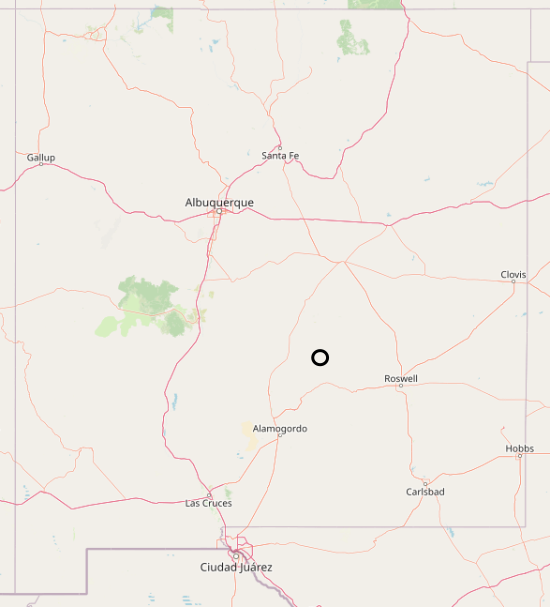
Here’s a topo map that would fit inside the circle:
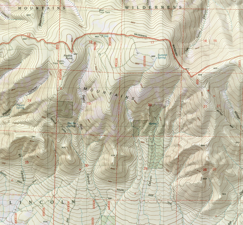
Here’s how it looks in Google Earth:
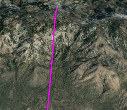
And finally, here’s the elevation contour along that magenta line:
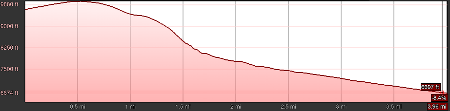
The numbers are hard to read, but at the top of the mountain, shown at the left, we have a large, rounded area at about 9,880 feet (3,011 m) above sea level. At the right, at the base of the mountain (corresponding to the bottom in the aerial views), we’re at 6,674 feet (2,034 m). So the elevation drop is about 3,206 feet (977 m). Close enough to our target of 1 km, and it occurs over a horizontal distance of 4 miles (6.4 km).
The contour shows that the site isn’t really flat at either the top or the bottom, so the (claimed) ability of EPS to handle that situation would be a benefit here.
We estimated above that we need 864,000 square meters each at the top and the bottom for our storage fields. Google Earth makes it easy to draw a polygon by hand; if we limit the elevation to about 9,700 feet and above, it looks about like this:
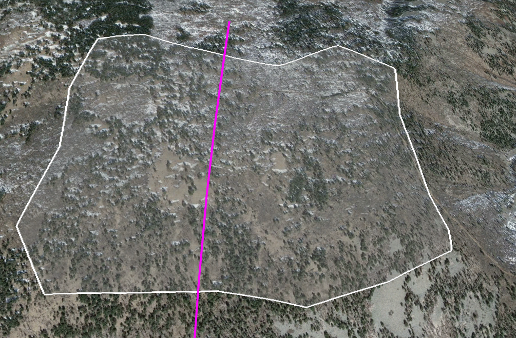
Google Earth will also tell us the area of this polygon, which is 1,486,000 square meters (149 hectares, or 367 acres). That’s about 1.7 times the area we said we needed.
At the bottom, as is usually the case, things are easier. If we limit the elevation range to about 6,500 to 6,750 feet, it’s easy to find an area of 3.2 million square meters that looks like this:
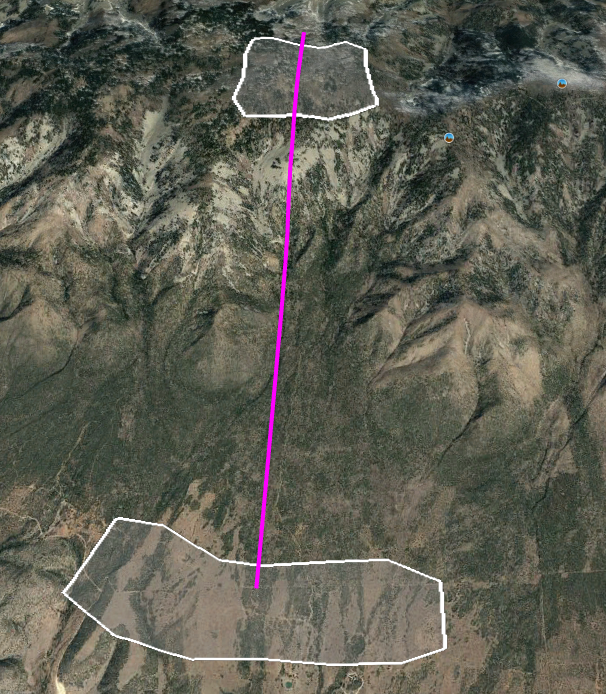
This is more than twice the area of the upper field, and there’s no reason for the two storage areas to be of different sizes, so we’ll be able to choose whatever subset we like from this lower area. (The magenta line is approximately where the penstocks would go, carrying water from the upper storage to the powerhouse, which will be located near the lower storage.)
Another good thing about this site is that, if Google Earth’s imagery can be believed, no people live there. (There do appear to be some ranches in the general vicinity, which might or might not be active.) It’s possible that it’s used for grazing, and like many desert places, it’s likely to be home to some interesting and fragile ecosystems. So disturbing it would do some damage, but it’s hard to think of a place in the continental U.S. of comparable size where the damage would be less. I don’t want to gloss over this issue, and there’s more to say about it. But it must also be kept in mind that global warming is damaging ecosystems everywhere on the planet at once, and will get much worse if we don’t do something to change our current course.
Where The Energy Comes From
The convenient topography is not the only reason I chose this location. Our purpose is to store renewable electricity for later use, and this part of New Mexico has some of the best combined solar and wind energy resources in the country. Here is part of a national wind potential map from the National Renewable Energy Laboratory:
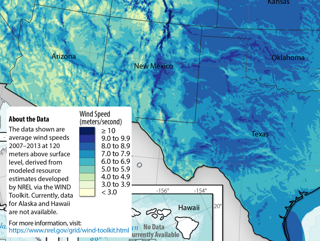
Texas and Oklahoma are well-known wind meccas, and far-Eastern New Mexico has some of that, but there’s also a strip of even windier territory in the South-central part of the state (the darkest blue under the word “Mexico” in the map), not far from the Capitan Mountains. Some big wind farms are being built right now in this area, such as a 298-megawatt farm in El Cabo.
And here’s a part of NREL’s solar potential map:
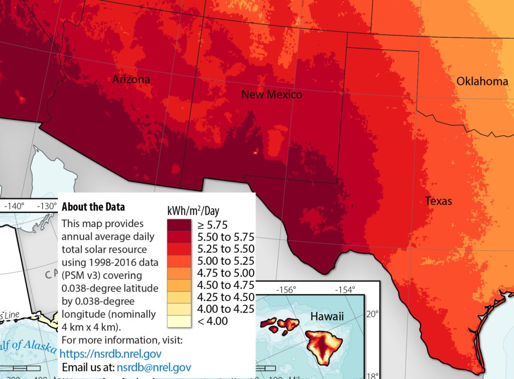
Southern New Mexico has some of the very best solar potential in the nation, too, again not too far from our site. We’ll need transmission lines to carry power from these generation areas to our location, and from there to the major PNM markets, so in a later post we’ll research what lines are already in place, or planned.
But for now, this site will do fine for our imaginary encapsulated pumped storage facility, which I’ll call the “Capitan Site,” and which I’ll continue to use to examine EPS in more detail.
Key Numbers:
| Attribute | Metric Units | Imperial Units |
| Energy Stored | 10 GWh | (same) |
| Peak Power | 400 MW | (same) |
| Head | 1000 meters | 3281 feet |
| Water Volume | 3.6 million cubic meters | 3,000 acre-feet |
| Area Per Storage Field | 864,000 square meters | 213 acres |
| Water Flow At Peak Power | 40 cubic meters per second | 1,413 cubic feet per second |
Previous: Encapsulated Pumped Storage, Part 4: Some Storage Basics
Next: Encapsulated Pumped Storage, Part 6: Powerhouse Components
- see https://www.eia.gov/opendata/qb.php?category=3390080
- this will be revisited in Part 13.