The EPS system divides neatly into two subsets. One subset is unconventional: the water storage systems at the top and bottom. These systems are different from normal reservoirs in every way.
The other subset is the powerhouse components (turbines, pumps, motor/generator units, and related pipes and valves), and the penstocks (the pipes connecting the upper and lower elevations). These are very conventional: they work the same way and follow the same laws in EPS as in any other pumped hydro storage system. All these have been studied so thoroughly in the last 100 years that EPS is not likely to bring any major innovations to the table. What’s good about this is that the hard work has been done, improving the odds for rapid deployment and predictable costs. (But that’s only true in a relative sense, because every pumped hydro system built to date has been a unicorn, custom-designed for a particular site—you can’t order one from a catalog. One thing that we can try to do is to standardize: pick one model of turbine and one model of pump, and stick with them, for example.)
This post is an overview of the conventional, but complex, components inside the powerhouse. The motor/generators, the turbines, and the pumps (if separate from the turbines) are where energy is exchanged between water and electricity. They will significantly influence the system’s overall cost and efficiency. We’ll cover this now because choices made here will have an effect on the physical layout and other aspects of the system.
First we need to talk just a little about the electric grid and its management. The grid’s job is to move energy, in the form of alternating current, from generators to customers, at a highly predictable voltage and frequency. As customers draw more power, voltage and frequency will start to sag, and the grid operators take action to compensate (e.g. by increasing generation) to get everything back to normal. Because both supply and demand constantly fluctuate, and because the grid is a complex and spatially distributed set of transmission lines and other components, this is not an easy task. As the percentage of overall generation made up by wind and solar increases, while steadier sources such as coal decline, the fluctuations are getting bigger. Grid managers depend on a complex range of so-called “ancillary services” to help them keep the grid stable. These operate at different time scales, from fractions of a second to hours. In this world, the variability that wind and solar introduce is just one factor among many.
A key decision for hydroelectric storage, mentioned earlier, is whether to use turbines that can serve double duty by running in reverse, as pumps, or to use separate, dedicated turbines and pumps (called a “ternary” arrangement because there are three main components: the turbine, the pump, and the motor/generator). Both schemes work, and are well-proven in practice. There are also more purely electrical choices, like fixed-speed versus variable-speed, with their own trade-offs. This detailed paper says in its summary,
“A number of different types of advanced pumped storage plants (advanced conventional, variable speed and Ternary) have been developed with special features to allow fast reaction time for firming the variable nature of renewable energy generation there.”
Any of these options will work with EPS; whether it’s worth more capital expense to build, say, a ternary system (the most costly) is mostly about how valuable the additional grid services it offers (e.g. quick switching from generation to storage mode) happen to be in a particular region. I’ve opted for a ternary system for the hypothetical Capitan site because it’s the most versatile, and it simplifies high-head operation (discussed below).
The reason that a ternary design is more versatile is that with a single turbine that also functions as a pump, if the system is in storage (pump) mode and needs to reverse, it must first come to a safe stop; then, in most cases, it must be “dewatered” (the turbine cleared of water using compressed air) before it can start rotating in the opposite direction; then the speed must ramp up again before effective generation can begin. This can easily take many minutes. In a ternary design, the motor/generator is on a common shaft with both the turbine and the pump, with clutches provided to control which is transmitting power. This can lower the reversal time substantially and enhance the usefulness of the storage facility to the larger grid.
Aspects of grid management that don’t pertain to pumped storage per se won’t be covered here—the paper referenced above, and this one about the Gordon Butte plan, give more details.
Operating At High Head
The Francis turbine is the type most commonly used for reversible operation, partly because it’s efficient in both modes under a wide range of conditions. Since we’ve decided against reversible operation for this use case, we have other choices. Francis turbines are seldom used for very high-head situations, i.e. above 600 meters1, although this limit can apparently be pushed (Hitachi describes a system with 700m head2). In any case, if we forego reversibility, there is a turbine design which has proven (over generations) to operate in very high-head situations with excellent efficiency. This is the Pelton turbine, or Pelton wheel (seen before in this blog).
In fact, the world’s highest-head hydroelectric (generation, not storage) plant, the Bieudron Hydroelectric Power Station3 in the Swiss Alps, uses Pelton turbines. There are three, each rated at 423 megawatts. The hydraulic head is an amazing 1,869 meters, producing a pressure of 203 bars or 2,944 psi, and the efficiency is over 92%.
In hydraulics, it’s a truism that turbulent flow dissipates energy as heat, and laminar flow is much more efficient.4 There are two keys to the efficiency of a Pelton turbine, and the first is not really part of the turbine itself. It’s called a spear valve (shown below; the few online images of spear valves that exist, like this one, are clearly very old—I’ve had no luck determining who invented it). The spear valve converts high-pressure, low-velocity water into a jet of very high-velocity water at low pressure, at any flow rate in its range, without introducing efficiency-robbing turbulence. A commercial Pelton turbine is normally driven by anywhere from one to six spear-valve nozzles.
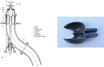
Once the spear valve has produced a very high-velocity (hence high-energy) jet of water, that jet hits a Pelton bucket (sometimes called a spoon). The bucket is also carefully designed to maintain laminar flow. Its sharp edge in the center splits the jet of water in two. Then the curve of each bucket half gently steers the water in a 180° curve, sending it back in the direction it came from. Under ideal conditions, where the bucket is retreating from the jet at one-half the speed of the jet itself, the energy of the water is completely transferred to the bucket; the water, now motionless, simply falls under the influence of gravity. Through the action of the spear valve and then the bucket, all of the energy stored in the high-pressure water coming in has been converted into rotary motion of the turbine runner; this is the definition of 100% efficiency.
In practice, of course, there are some losses due to various imperfections. Any defect in the geometry of the valve or bucket will disrupt the perfect laminar flow. One issue with Pelton turbines (and other types as well) is that the water in hydroelectric systems normally carries silt, sand, and larger debris—anything small enough to pass through the intake screen. These solid particles (especially sand and rocks) cause wear in the valve and bucket surfaces, lowering efficiency and requiring periodic maintenance to repair or replace the surfaces. The knife edge of the bucket is especially vulnerable to damage. A finer screen at the intake helps, but at the cost of energy-wasting back pressure in the screen itself.
In an EPS system, solids can be filtered out of the water when it’s put in, and because it’s fully enclosed, there’s no way for silt or other debris to get in later, so the valves and buckets should work at top efficiency for a very long time before needing maintenance.
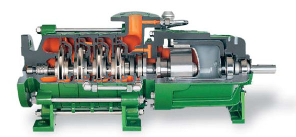
It’s pretty obvious that the Pelton wheel is not a reversible design. Spinning the buckets with a motor will not draw up water and send it back through the spear valves. So the pumping phase of pumped storage requires a different device, a centrifugal pump:
Pumps like this one, with a single impeller, can only raise the pressure a small amount. For higher pressures, multiple stages (which are basically separate pumps, but running on a common shaft) are arranged in series, sequentially raising the pressure.
This design is very versatile, and pumps are commercially available at almost any flow rate and head rating. As with turbines, consistently clean water reduces maintenance issues and extends equipment life.
The motor/generator (virtually all pumped hydroelectric systems combine these functions in a single device that can operate in both modes) is no different in an EPS system than in a conventional pumped storage system, and so it won’t be discussed here. The same is true for the purely electrical components relating to the motor/generator and its connection with the grid.
Positive And Negative Pressure
At its inlet side, a pump exerts suction. It lowers water pressure so that higher-pressure water in its feed tube will be driven forward by the pressure difference, into the pump. That’s the nature of any pump, but it creates a limitation when pumping water from a source that’s at or near 1 atmosphere, such as an open tank or reservoir. The limitation is that as you lower the pressure on water, its boiling point gets lower, and eventually it will boil at room temperature. The pump will then stop working, as only water vapor and not liquid water is coming into the pump body. But even well before that point, the lowered pressure will make the pump more vulnerable to cavitation damage5. Cavitation occurs when tiny vapor bubbles form in the water and subsequently collapse against interior wet surfaces (such as pump impellers), causing microscopic erosion of metallic and other materials. It’s extremely destructive to hydraulic equipment of all kinds, and must be prevented.
The way cavitation is suppressed (aside from design changes) is usually to operate the equipment at high enough pressure to inhibit the formation of vapor bubbles. This article defines net positive suction head available (NPSHA) as a figure of cavitation safety. Water that is hot (e.g. from sitting in bags in the sun) has higher vapor pressure, which reduces the safety factor and must be taken into account. Quoting from that article:
The available energy is best expressed as NPSHA, which is the difference between the pressure at the pump suction nozzle and the liquid vapor pressure.
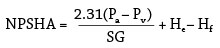
Where:
Pa = pressure at the water surface in psia
Pv = vapor pressure for the fluid at the given temperature in psia
He = difference in height from water surface to the pump suction centerline in feet
Hf = suction line friction loss in feet
SG = specific gravity of the fluid
Hot water systems tend to have low NPSHA, which puts them at risk for cavitation at the suction eye of the impeller. As the liquid accelerates through the suction pipe, pressure drops. Bubbles will form as the liquid drops toward its vapor pressure.
After the bubbles enter the impeller eye, the pressure begins to increase and the bubbles collapse. The collapsing bubbles produce tremendous localized pressures on the impeller’s surface and remove small amounts of metal. The tiny abrasions occur constantly as the liquid moves through the pump and, over time, will severely reduce the structural integrity of the metal. When pumping water, cavitation typically sounds like rocks hitting the impeller.
For a hydroelectric pump, higher water pressure is obtained by locating the pump at the lowest part of the system, lower than the storage field, so the pump benefits from added head pressure. This article states:
“Reversible pump turbines have strict design-specific submergence requirements to suppress destructive cavitation and must therefore be installed well below tailwater level, typically in an underground powerhouse.”
There seems to be no way around this requirement, so we’ll just accept it. (“Tailwater” refers to the water exiting the turbine.) The pump must be located at a a lower elevation than the lowest point in the lower storage field. Doing the NPSHA calculation indicates that, if the lower storage piping system is reasonably free-flowing, we could locate the pump at the same elevation as the lowest point of the lower storage field and be safe from cavitation. We’ll need a much more detailed analysis (via a CFD computer simulation of the storage field) to get a more refined answer than that.
How about the location of the turbine? First of all, you may be wondering whether a Pelton turbine is also vulnerable to cavitation. Here is a very detailed paper; in general, a properly designed Pelton turbine has low cavitation risk (they are much more affected by erosion due to silt in the water, which as mentioned above, is not a concern with the fully enclosed water system of EPS).
But getting back to the question of where the turbine should be located: as I mentioned, when a Pelton turbine is running, the water at the exhaust essentially “falls out the bottom” of the turbine housing at 1 atmosphere. From there, we need to get the exhaust water out of the way and into the lower storage field fast enough at full-power flow, or it will back up and interfere with the turbine. In a normal pumped hydro configuration, this water is collected into a “tail race,” which is the conduit carrying water exhausted by the turbine back to the lower reservoir—commonly a sloping canal that leads into the open lower reservoir. As long as the tail race is wide and deep enough, getting the water down a modest elevation change into the reservoir isn’t a problem, even at full flow.
NOTE: This post does not reflect my latest thinking on water storage. Please see the new summary.
With EPS, however, the reservoir isn’t an open pond, which complicates the situation. That water will be flowing through pipes and valves, and into bags, whose inlet pressure will gradually increase as the water rises in them; and we will definitely want to be able to exploit the EPS feature of siting the bags at moderately different elevations. In order for all of this to gravity-feed fast enough, we might think about locating the turbine at a substantially higher elevation than the storage field, to give us more head pressure to drive the process.
But we just noted that we must locate the pump below the storage field elevation, to prevent cavitation. These two observations imply that we would like to locate the turbine a considerable distance above the pump. And that’s a problem because, in the preferred implementation, there is only one motor/generator that shares a common shaft with both the turbine and the pump. We would have to have an unusually long vertical drive shaft to span this vertical distance. That isn’t the most intractable mechanical engineering problem in the world, but we’d rather not have to deal with it.
We might solve the problem with an auxiliary pump, located below the lowest point of the storage field, to pre-pressurize the water flowing into the main pump. This pump (which would need a separate motor) would add cost and complexity.
Another idea I’ve had, which I haven’t seen described before (in my very minimal exposure to the literature), is to run the Pelton wheel in air that’s slightly above 1 atmosphere. Normally, the open bottom of the housing keeps the air at ambient pressure, but what if it were enclosed? The volume of air inside the housing will be constant to a first approximation (the volumes of water flowing in and flowing out are equal, by definition). In the chaotic flow of the water after its contact with the turbine buckets, we’d expect some air to be entrained into the water, and that air would have to be replaced. An air compressor could make up losses and keep the housing at a pressure sufficient to push the water slightly uphill, into and through the storage field at the necessary flow rate. (Naturally, keeping the housing above 1 atmosphere will reduce the turbine’s power output slightly—the energy to maintain that pressure has to come from somewhere.) Whatever air is entrained into the flow should be allowed to leave before the water enters the storage field, which might require a long chamber of smooth flow where the air can rise to the top and escape. (Or it’s possible that an air vent at the top of each bag could let the trapped air out.)
If this idea is workable, the turbine and pump can be co-located on a shaft of reasonable length, a small distance below the elevation of the lowest part of the storage field. No part of the system would be open to the atmosphere. Clearly, there are unanswered questions to be worked out in this part of the design, and so there is technical risk until these questions are answered. Light may be shed by more research into how other pumped-storage facilities, with a ternary powerhouse arrangement but with conventional reservoirs, solve this problem. (There aren’t many in production yet.) If the powerhouse does need to be the lowest point in the system, any location where the lower storage field is on an alluvial plain that slopes gently away from the base of the mountain (such as the Capitan site) will need some excavation to accomplish that.
The situation at the upper storage field is much simpler. The collapsible bags connect by pipes to larger manifolds, designed to minimize hydrodynamic losses, and these connect directly to the penstocks that carry water down the large elevation drop to the powerhouse. The fact that the pressure in the bags increases as they are filled is actually beneficial here; it stores a bit more energy, and during discharge, that pressure will help keep the water flowing into the penstocks at the necessary speed. We want to avoid pressures much below 1 atm anywhere in the system, including the upper storage, but cavitation damage isn’t a concern because there’s no actual hydraulic machinery at the upper end.
Previous: Encapsulated Pumped Storage, Part 5: An Interesting Scenario
Next: Encapsulated Pumped Storage, Part 7: Layout And Plumbing
- Wikipedia
- hitachi.co.jp
- Wikipedia
- I didn’t find an internet resource explaining the two that I really liked, so Wikipedia’s will have to do for now.
- wikipedia