NOTE: This post does not reflect my latest thinking on water storage. Please see the new summary.
Now we can talk about how our water tanks and other components will be placed on the site, and connected together to form a complete system. Here’s an idealized system diagram, in cross-section:

Typically there will be more than one turbine, pump, motor/generator, and so forth, to increase water and power capacity, and to allow a unit to be taken out of service without shutting down the whole facility. (The number of penstocks can match the number of turbines, but in many systems that relationship isn’t one-to-one. We might choose to have only one penstock because it isn’t a component that’s likely to fail.)
No assumptions are made at this point about how the penstock is installed—it could be mounted above-ground, buried in a shallow trench, or completely in-ground in a tunnel.
One of the stated goals of EPS is rapid installation of standardized components, which would be well served by choosing one standard combination of generator/motor, turbine, pump, and plumbing within the powerhouse. This would be a “slice” of storage, and the system could be scaled up quickly by adding more slices.
Here’s an overhead view:

A real system would have many more bags, but this shows how the bags could be laid out in a fairly dense arrangement, and connected by a series of pipes of increasing size (to limit hydrodynamic losses as the aggregate flow rate grows larger).
The bags that will be shown here are modeled after “pillow tanks,” which are not the only alternative (as will be explored later), but are a reasonable starting point, given that they hold a lot of water relative to the amount of material required. This cross section shows part of a single bag in situ:

The terrain has been leveled and smoothed to support the weight of the filled bag without damaging it. A single pipe, shallowly buried to protect it from freezing and damage, both supplies water to the bag and drains it. There is no air in the bag at any point, and as water is withdrawn, the flexible bag collapses to (almost) zero volume. The pad is very slightly sloped so that the feed pipe enters the bag at its lowest point, to prevent trapped water.
The feed pipe, with an elbow, is permanently attached to the bag, but a removable flange arrangement allows it to be separated from the supply pipe, so the entire bag (when empty) can be lifted off its pad and replaced with a new bag. Inside the supply pipe, a transient valve, which can be operated remotely by the control software, allows the bag to be isolated. The most important reason for this valve is an EPS feature discussed earlier: the ability to locate bags at slightly different elevations within a storage field. Another benefit is that if a bag needs to be replaced, it can be drained through the supply pipe, and the transient valve closed. In this state, removal of the bag doesn’t cause any significant loss of water. The transient valve would be housed in a box set into the ground, so it can be accessed for inspection and maintenance. (It looks like a butterfly valve in this diagram, but that’s just for illustration.)
That’s one style of bag location and attachment, but there are other options. Here is another variant that:
- Has the feed pipe attached at the center of the bag, not one edge;
- Has the bag sitting in a slightly cone-shaped “pit” or shallow depression, to minimize friction losses as water enters or leaves the bag; and
- Provides the bag with a large, circular flange that attaches to a flare at the end of the feed pipe. This will improve flow, and the surface attachment will simplify installing or removing the bag.

Let’s choose, for our Capitan prototype, some dimensions for the storage-field components. The volume of water per bag is a key number. Here we have a challenge, one that pervades this system in which low cost rather than cutting-edge technology is the main goal. We want to minimize cost over the life of the facility. So, what does it cost to bulldoze a flat pad, on top of a hill, as a function of size? What does it cost to turn rolls of flexible tank materials into bags by plastic welding, as a function of size? We don’t know enough to answer these questions yet, so we’ll pick something that seems reasonable until we can talk to experts in those areas.
What would happen if we had 1,000 bags in each storage field? That’s a lot of bags, but we need 3.6 million cubic meters of water1. So the volume per bag would be 3,600 cubic meters (951,000 gallons). If the bags are 5 meters tall when full, their area would be 720 square meters. If square, that’s about 27 meters on a side. (Pillow tanks this big aren’t available off the shelf, but there’s no reason they couldn’t be made.) I’m pretending for now that the water in a bag assumes the shape of a rectangular prism, which isn’t true, but is close enough for this exercise (we might have to add a few bags in the final design to compensate).
Now we can ask whether bags of these dimensions would be compatible with the site we’ve chosen. All the elevation data is freely available, so we might as well leave the playpen of Google Earth and start doing our own elevation profiles2.
Here’s an elevation profile across the width (East to West) of our Capitan upper storage area (as shown in the Google Earth image below).
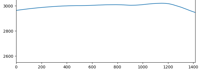
Here is the same image, with some of the 27 x 27 x 5 meter bags we’ve specified added to give a sense of scale:

Here is an image of the Capitan upper storage field, overlaid with 64 groups of 16 bags each, for a total of 1,024 bags:

We are already a bit over our spec of 1,000 bags, and there appears to be room for more. Each white square represents a single 27 x 27 meter bag. Some extra room is left between groups for the distribution piping, which will be studied in more detail later. (Whether this is the best way to position the bags needs more study too.)
To check the math, let’s compare this to the reservoirs of the Gordon Butte facility. Their project overview says, “Each reservoir will be approximately 4,000 feet long and 1,000 feet wide with depths of 50 to 75 feet,” and “Reservoirs [are] sized at approximately 4,000 acre-feet.” 4,000 acre-feet is 4.93 million cubic meters, and 4,000 x 1,000 square feet of surface is 372,000 square meters. This leads to an average depth of 13 meters—43 feet.
By comparison, our Capitan water volume is a little smaller, at 3.6 million cubic meters. Our upper “reservoir” is shallower, 5m versus 13m. But our surface area is bigger, at 625,000 square meters. So we end up storing 37% less water than they do.
Our energy storage, 10 GWh, is considerably bigger than theirs (which they don’t state, but which I calculate to be 4.3 GWh). This difference is due to our EPS system having 1000m head, versus 314m for Gordon Butte. So the math looks good.
Previous: Encapsulated Pumped Storage, Part 6: Powerhouse Components
Next: Encapsulated Pumped Storage, Part 8: Pressure Regimes
- per Part 5
- The data is from The National Map, processed in Python using the gdal package.