In a recent post, I mentioned that the water storage aspect of EPS is very unconventional, while the rest is very conventional. Those two aspects are also very different in terms of the water pressures they deal with, which has a big impact on materials and costs.
We can divide the system into three pressure regimes:

The upper and lower storage field regimes are dedicated to storing large amounts of water as cheaply as possible. Holding and guiding all that water will take a fair amount of material (though far less than in most reservoirs), but fortunately, the pressures in those regimes are relatively low.
The high pressures are confined to the middle part, the penstocks and the powerhouse components. The materials in this region need to be very strong, but their work happens in a much smaller space, which keeps the amount of expensive material under control.
“High pressure/high cost” and “low pressure/low cost” are relative terms. 100 psi of pressure is low enough that “garden-hose technology” can be used to manage it, though the large scale means paying more than garden-hose prices; 1400 psi is an entirely different challenge, and everything will cost more. The key to cost control is to only use expensive materials when you have to.
The penstocks are where the transition from low to high pressure takes place. At the top of a penstock, the pressure is one atmosphere, or slightly more. As you descend through the penstock, the accumulating weight of the water column causes the pressure to increase (at 0.43 psi per foot, or 0.097 atm per m) until it reaches its peak where it enters the powerhouse. At 1 km head, that peak is 1,422 psi (96.8 atm).
The pressure then abruptly decreases. If the water’s flowing down through the Pelton turbine, it comes out of the spear valves at 1 atm, or 14.7 psi1. If the water’s flowing up through the pump into the penstock, the pump has to compress it from a little more than 1 atm up to 96.8 atm. Either way, a lot of energy is being transferred into or out of the water in a very small space.
Below the turbine and generator is the tailrace, and from there on into the lower storage field, everything is in the garden-hose pressure regime of about 0 to 100 psi above atmospheric pressure.
Note that these are static pressures—the pressures that will occur if the water is not moving, or is moving very slowly. During rapid flow, the static forces will still be in effect, but dynamic forces will further modify pressure at each point. Steady-state flow will cause loss of pressure along the length of a pipe, due to friction losses. And sudden changes (such as opening or closing valves, or turning a pump on or off) will cause pressure transients, which can be quite significant (and destructive, e.g. “water hammer”).
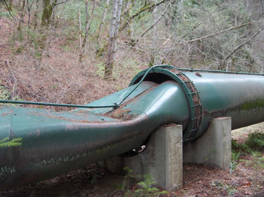
Pressure transients are most important in the penstocks. When the system is in a steady state of generating power at its maximum capacity, the whole mass of water in a penstock is moving downward as a unit, all at the same velocity (which depends on the combined cross-sectional area of the penstocks). This means the water has a great deal of momentum. If the flow were to be suddenly shut off at the powerhouse (e.g. because power demand from the grid had abruptly decreased), the mass of the water would resist being suddenly stopped, resulting in a large positive pressure transient (spike) which could easily burst the penstock. If, instead, valves were closed at the top of the penstock to try to stop the flow, a large negative pressure transient would occur, which would tend to implode the penstock, like this:
One way to avoid this situation is to always change the system’s operating conditions very gradually. If the same valves are shut off very slowly, then the pressure transients will be much smaller. This slow-change protocol should be followed whenever possible, but if the plant is providing services to the grid that require rapid ramp-up or ramp-down of power, then correspondingly fast changes to the hydraulic situation might be necessary.
In the case where generation needs to be ramped down quickly, if we’re using a Pelton turbine, we can insert a deflector plate between the spear valves and the turbine buckets, causing the water streams to miss the turbine entirely, and resulting in a sudden drop in power (this scheme assumes we can dissipate the energy in the water streams, which hasn’t gone away, as frictional heat, without damaging something else). Then the valves can be closed at a slower, safe rate to stop the water flow. Another approach is to have other valves in the system, similar in size and design to the ones driving the turbine, but not aimed at the turbine buckets. By opening these valves quickly, but in perfect sync with closing of the actual turbine valves, a pressure spike in the penstock can be minimized, while power generation ramps down quickly. (Fast ramp-up could be attained by reversing the process, but this would require the bypass valves to be gradually opened prior to need, which would waste stored energy. So this would only be useful when a sudden increase in power demand can be anticipated, which won’t normally be possible.)
To protect the system from pressure transients, nearly all hydroelectric sites include one or more surge tanks, which are air-filled chambers that allow water in and out. These are often connected to the penstocks and may be quite large. The air in the surge tanks acts as a spring to absorb excess energy from a pressure transient (and return it in a safe manner). This will be discussed more later. In any case, all these phenomena in the penstock and powerhouse are the same in EPS as in any other pumped storage facility, so no wheels need to be reinvented in this area.
The high and low pressure regimes call for different materials. All of the low-pressure components call for FRP (fiber-reinforced polymer) solutions, which are affordable, long-lived, easily mass-produced or custom-made, and available from many manufacturers over a wide range of physical properties (such as temperature and pressure resistance). They also generally are smoother inside, both initially and over their life cycle, than steel pipes, resulting in lower friction losses. The use of pre-fabricated, plastic components for the storage parts of the system—instead of large-scale earthworks, concrete, and steel—is a key reason why EPS should be both cheaper, and much faster to build, than traditional pumped storage.
Steel is an obvious and common choice for the high-pressure water-handling components (pumps, turbines, shafts, and the pipes and valves within the powerhouse. Steel is also a predictable choice for a penstock, but we should keep in mind that the pressure decreases linearly as we move from the powerhouse to the upper storage elevation, so we shouldn’t discount the possibility of using FRP materials in lieu of steel for part of the penstock (or even all of it—a notion we can’t reject until we’ve talked to some vendors, because FRP technology is improving all the time). The penstocks will make up a significant part of the total facility cost, so we should always look for ways to make them less expensive.
Previous: Encapsulated Pumped Storage, Part 7: Layout And Plumbing
Next: Encapsulated Pumped Storage, Part 9: Transient Valve Operation
The photo is stunning–it’s easy for me to visualize a pipe bursting from pressure, but I wouldn’t have though that it could implode like that. Kind of cool, actually.
It’s also cool that your project has a guiding aesthetic of low cost and easy implementation. I ignored that as I started thinking about reducing turbulence in pipes. I remembered that in the 80’s, there was a revolutionary America’s Cup boat that used simulated shark skin to create a rough texture that, counter-intuitively, made the boat go more smoothly and quickly through the water. The rough bits, called “riblets,” broke up the vortices of water that slowed the boat.
So I did a search to see if this had been applied to pipes, and found some journal articles:”Drag reduction in pipes lined with riblets” (AIAA Journal); “A preliminary assessment of the feasibility of using riblets in internal flows to conserve energy” (ScienceDirect); and “3 Ways to Cook Riblets on the Grill” (wikiHow). One problem with riblets is that they can get dirty and lose effectiveness, but the closed MPS system keeps the water clean, and…
Um, insert forehead slap here: as you said above, no need to reinvent the wheel. There are surge tanks for this problem. So now I’m wondering if the humble bag (not to be confused with the humblebrag [which this may be]) could come to the rescue: just sling a bunch of bags under or near the pipes as surge tanks? You say surge tanks can be “quite large”–can a number of smaller (possibly linked?) bags do the same job?
Anyway, great stuff, keep going!
0
Your “riblets” search, besides making me want to fire up the smoker, reminded me of having seen something a long time ago about using an engineered equivalent of fish slime as an interior coating for things like penstocks. Can’t find it now. The idea was not only to reduce initial friction (which fish slime does amazingly well), but also to prevent buildup of algae etc. inside pipes, which makes the pipe bumpy instead of smooth, and costs a lot of efficiency (until you shut the facility down for expensive cleaning). Going to search for your riblet results now.